2. The Spark Generator Board
2.1. Study of the Spark Generator
2.1.1 What is a Spark Generator ?
In most vehicle's petrol engine the explosion is provided
by a spark. The classic system is to generate it when the piston is at the top
of its travel within the cylinder, it is said to be at Top Dead Centre (TDC).
It is from here that the angles are measured i.e. it is 0°.
 For an optimum explosion, a spark has to occur some time before the Top Dead Centre
to allow the mixture of petrol and air to be burning when the piston reach the
Top Dead Centre. This is known as the advance angle since the spark occurs «in
advance of» Top Dead Centre.
For an optimum explosion, a spark has to occur some time before the Top Dead Centre
to allow the mixture of petrol and air to be burning when the piston reach the
Top Dead Centre. This is known as the advance angle since the spark occurs «in
advance of» Top Dead Centre.
For best engine efficiency, the advance angle is small for
low revolution rates and much larger at high revolution rates.
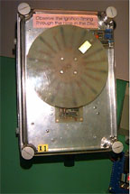
In this project we use a large plastic box containing an electric
motor and some electronic components, the whole simulate some aspects of a petrol
engine.
With this simulator we set the advance angle at 10 degrees
at 3 revolutions per second and about 26 degrees at 10 revolutions per second,
with a linear angle between these two rotation rates.
2.1.2. Tests with the 68HC11
The Digital Systems Laboratory has a complete set of software
and hardware package to use the popular Motorolaõs 68HC11 microcontroller chip.
The software used are :
|
Programmerõs File Editor (PFE)
|
to enter and edit the C program (source) files |
|
C68 compiler
|
to translate C to 68HC11 runnable (hex) files |
|
Download
|
to move the hex file into the 68HC11 memory |
|
HyperTerminal
|
to communicate with the 68HC11 |
The advantage of the 68HC11 is that we can use the testing board to perform real time
test quickly thanks to the C compiler. The engine simulator
17 In the following C source code, we can see the algorithm
used to calculate when the next spark must be generated, as we can see the complexity
of the equations used. As far as the floating point format can't be used because
it's slow, we have to dispose the equation so that we avoid the integer range
limitation.
for(;;)
{
while( (PortA & 0x01) == 1);
while( (PortA & 0x01) == 0);
t2=TcnT;
if (t2>t1) rotation = t2-t1;
else rotation = ( 65535 - t1 ) + t2;
d = ( 2*( 10000/( rotation/100 ) ) + 22 )/7;
t_temp = t2 + rotation - rotation / 360 * d;
Toc1 = t_temp;
Toc5 = t_temp + 4;
t1 = t2;
}
We count the number of clock cycles between each pulse, which
calculates the time duration of a single engine revolution. Here a clock cycle
is 8us.
Thanks to the HyperTerminal software we can obtain the result
of the calculation in real time and use it to create a graphic with Microsoft
Excel.
As we can see on the graphic, the measures are very close to
the theoretical curve. The result is obtained with the use of two equations
including multiplication and divisions on integers.
2.1.3. Implement the spark for VHLD
But the final purpose is to implement the spark algorithm
in VHDL and use an Altera chip, which is in fact using a pure logic component.
The only division with VHDL is a division by a power of 2, which is in fact
the use of a shift register. That means that we can use only linear equations,
and so we have to use an other approach to implement the spark angle calculation
in VHDL.
Another way is to represent the spark angle in function of
the number of revolution per second. In the graphic of this representation,
we can see that this representation is linear.
We are looking for the spark angle, but the final information in the algorithm is
in fact the time information : «when the spark should occur ?».
So we represent the time of the spark depending on the duration
of a full cycle. The equation of this representation is : y = 0.9913*x - 794,14
As the use of floating variables was too slow with the 68HC11,
it is not possible with an Altera chip (whereas it could be possible with larger
components ).
Hopefully 0.9913 is very close to 1 -1/128, which can be implemented
in logic functions.
The resulting equation is : y = x - x / 128 - 8.
The results diverge for longer cycles, which means in fact
slower speed, and so it's less critical. The representation spark angle/Number
of cycles per pulse show that the angle error never exceeds 1 degree, which
is the best result we can attempt from an integer calculation.
The Linear curve represents a first attempt to implement the
spark algorithm, which consisted in partitioning the curve in 3 linear parts.
But it proved too difficult to implement.
The Series2 curve represents the last choice, more simple
and in fact more precise.
For any comment/Pour tout commentaire :
stephane@odul.net