The VHDL, as any language, needs a compiler. the most popular VHDL compiler is the compiler provided in the Integrated Development Environment from Altera, called Max+PlusII. This environment supports many ways to develop hardware components, like AHDL (Altera Hardware Description Language), or a schematic editor.
The Max+PlusII software provide all the tools necessary for the development of the Programmable Gate Array (FPGA) chips. Those include a text editor, a schematic editor, the compiler, a waveform editor, a simulator, and a programmer to download the program into the chip.
In order to simulate a VHDL component we have to create a waveform file. In this file we declare the value of the input signals, and declare the output signals we want to simulate. Then we start the simulation.
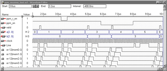
Simulated signals of the PPM system

The signal a[2..0] is the input value of the PPM emitter, and b[2..0] is the output value of the PPM receiver. The line signal is the PPM signal on the «line» between the emitter and the receiver.
Some of the memory bits of the PPM receiver are shown on this simulation. We can see how those bits are evolving during the time corresponding to the value of the PPM signal.
The valid signal indicate when the PPM receiver detects a «valid» signal. It is useful to differentiate a long signal from two signals with the same value.
 The Digital System Laboratory is equipped with a testing
kit for each computer with the Max+PlusII software.
The kit is composed of an Altera board, a logic analyser, and an oscilloscope.
The Altera board has an Altera EPF8452ALC84 chip which is used for each project. The memory of this chip is volatile though it is necessary to use an external EPROM for stand alone projects.
The board has 4push buttons directly connected to the chip, 2 hexadecimal switches, and 2 hexadecimal displays. Those last components are accessed using a data bus.
In order to test the PPM system, we used one of the hexadecimal switches as the input signal for the PPM emitter and a hexadecimal display as the output for the PPM receiver.
Two push button were used as enablers.
All the signals have been forwarded to the logic analyser to watch their state during the time.