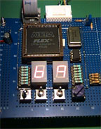
 Of course the Altera chip is not efficient alone. So we made a board with various components:
Of course the Altera chip is not efficient alone. So we made a board with various components:
The technique used for wiring the board is the wire wrapping method. This is faster to create a prototype board than the classic boards, and the possible future modifications are limited to the physical dimensions of the board.
After a few corrections in the wire wrap connections, and the inversion of the polarity of the displays, the board is working perfectly. A few tests are performed on the board and show that the spark angle correspond to the theorical value.
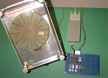
The Spark Generator Board
and the Engine Simulator